Four Rounds, One Diagram
Part III. Lesson 9. The Layered Flow Diagram.
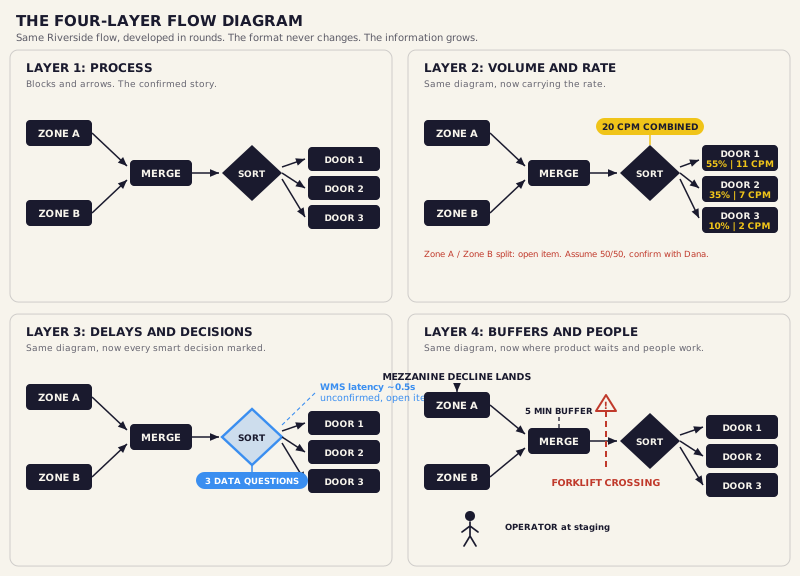
Last lesson you walked out with Riverside's Layer 1 flow. Dana looked at it and agreed that's her operation. That agreement is the whole point of Layer 1.
Here's what surprises new engineers every time. You don't open a new document. You pick up the same diagram you just got signed off and you start adding to it. Round by round, it grows from a picture of what happens into a specification of what the system has to do. The format never changes. The information on it does.
Layer 2
On every stage of the flow, note the rate the system has to carry there: cartons per minute, peak conditions, any seasonal note. For Riverside that's 20 CPM at the combined output, split back across the three doors, worked back through the merge to each zone's throw-on line.
This is the layer that reveals where the system works hardest. Layer 2 records what the rate needs to be. It doesn't work out what that costs in belt speed. That's Lesson 10.
Layer 3
Add the things easy to leave unsaid: dwell times, manual process speeds, scan rates, known constraints. Its real work is making implicit assumptions explicit so they can be challenged before they turn into design errors. An unconfirmed number is an open item, and you mark it as one.
Layer 3 is also where you mark every point the system makes a decision. At Riverside the big one is the sort. Every smart decision point has to answer the same three questions. Your job now is to write them down at each one. Not to answer them.
You're only planting these questions. How the system actually answers them is controls work, and that comes later, in Part V.
Take Riverside's sort decision point, where the system reads a carton and decides which door it goes to. Ask the three data questions about it, out loud. What does the system need to know? Who tells it, and from where? What happens if that answer is late? You're not solving the controls yet. You're proving the decision point is fully described.
Layer 4
Two things go on: where product waits, and where people are. A note like partial accumulation needs five minutes of buffer defines the accumulation requirement before anybody selects an accumulation conveyor.
Then people. A tech has to reach every drive and zone controller without pulling product or standing in live traffic. An operator needs a sight line. A layout that ignores this looks clean on paper and creates daily friction on the floor. You write the requirement, not the solution.
Writing vague buffer notes. "Needs some accumulation here" isn't a requirement, it's a shrug. It produces a vague accumulation design in Part IV that nobody can size or defend. Write buffer notes as explicit, measurable requirements: needs five minutes of buffer, must absorb this many cartons at peak, cannot back up into upstream equipment. Specific notes produce specific requirements that can be engineered to.

Once I build the flow diagram and get buy-in from the customer, the next step I take is to add details to that same flow diagram. Volume and rates, delays, assumptions, and notes. As I add layers to the diagram it becomes the map for the conveyor design. Every accumulation section, every speed decision, every sensor placement I make later traces back to a note on that diagram.
Take your confirmed Layer 1 diagram and complete the other three on it. Same diagram. Don't start a new one. Split 20 CPM across the doors, 55 to Door 1, 35 to Door 2, 10 to Door 3, and flag the Zone A / Zone B split as an open item. Mark the three data questions at the sort. Note Ray's half-second WMS latency as an open item, not a fact.
Hold it to the standard: a knowledgeable person could read your diagram and understand system intent, rate, control logic, and physical constraints, without asking you a single question.
Next, Lesson 10: Will this flow still hold when the rate gets real?