PART IV | LESSON 14: CHANGING DIRECTION AND ELEVATIONMATERIAL HANDLING ACADEMY
DRIVING QUESTIONWhat happens to the package when the system has to turn, climb, or drop?
THE STRAIGHT RUN ENDS HERE
A straight run of conveyor forgives a lot. Product drifts, rides a little cocked, sits closer to one rail than the other, and most of the time it still gets where it's going. A curve doesn't forgive that. Neither does an incline or a decline. Each one puts a specific set of forces on the package, and each one is a place where a correct static calculation still hands you a design that fails on the floor, because the engineer stopped at the number and never asked what the carton feels when the belt starts, when it stops, and when the load inside it slides. This lesson lives at those transitions, and it runs long enough to earn two sessions, because the two families, turning and changing elevation, break in different ways.
By the end of this lesson you should be able to run the curve requirement before you set any belt width and know why the curve drives the system, decide when a guardrail taper saves money and when it wrecks the product, take an incline or a decline past the static tumble angle into what actually tips a carton, validate it visually with the thirds method, and pitch a gravity section so product neither stalls nor runs away.
Session ACurves: the curve drives the system width
The diagonal, not the width
A package traveling through a curve occupies more belt than the same package on a straight run. Watch its corners: on the outside of the turn they swing outward, on the inside they swing inward, and the box sweeps a wider path than its own width. It's the diagonal of the package, not the width, that decides how much belt it needs to keep every corner inside the footprint through the turn. Get that one idea and the rest of curve design follows from it.
The Curve Formula turns that geometry into a number. Give it the inside radius of the curve and the width of the largest package in the mix, and it returns the minimum belt width that keeps that package's corners inside the belt all the way around. You run it on the Product Spec Calc, and the Calc Logic Guide is the authority for the arithmetic behind it. Here in solutioning you run the requirement to size the system; the locked, final-engineering precision on that between-frame width is the gap-and-capacity work, and that's Lesson 25. What you need now is the requirement and what it means.
What it means is that the curve output is almost always wider than the straight sections need. That isn't a preference, it's geometry, and it flips the usual order of design. The curve becomes the specification for the system, and the straight runs follow the curve, not the other way around. So you run the curve requirement first, before you commit any belt width. A curve whose width got guessed at is a curve that produces field problems, and by then the whole run is drawn around the guess.
Skew, the companion geometry
Curves have a cousin worth naming here: the skew. A skewed-roller section sets its rollers at an angle so product drifts against one rail and lines up across the belt, which is how you square cartons up before a scan or a merge. It's sized from the same envelope you just used for the curve, the widest and the longest package deciding how much skewed length it takes to align the narrow one without letting the long one hang off the end. The Calc Logic Guide carries that skew length; run it to confirm the section fits, and hold the tight number for Lesson 25.
The guardrail taper: rigid only
Now the trade. A wide curve can drive a wide run for a long way downstream, and wide conveyor costs more per foot than narrow. Sometimes you can claw that back with a guardrail taper: after the product clears the curve, guardrails funnel it from the wide belt down to a narrower one. It works, but only when every product in the mix is rigid. A rigid case rides the taper and never notices. A poly bag, a padded mailer, anything non-rigid catches at the transition and bunches, and you've traded a wider belt for a jam every shift. If you use a taper, it's a documented aesthetic and product-handling compromise, and you confirm the customer accepts it before it goes in the design. The priced version of that trade, wide belt against tapered belt in dollars per foot, is Lesson 29.
WHYThe curve requirement is almost always wider than the straight-section requirement, and it's a geometric fact, not a preference. Run it first and the system is specified correctly. Run it last and you've got a rework problem.
WHENAs soon as the layout shows a curve, before any belt width is committed, and again anywhere the material to be handled changes. Not when: Don't specify the straight-section width first and fit a curve into it. And don't reach for the guardrail taper to claw the width back unless every product in the mix is rigid. One poly bag in the mix and the taper transition becomes a bunching problem.
WHEREAt every curve. A curve that never went through the Curve Formula is a curve where the width was guessed.
FAILURE IF IGNOREDYou size the system off the straight run, then discover the curve needs a wider belt, and now the whole run has to change. Or you taper down after the curve to save money, the mix turns out to include padded mailers, and they pile up at the transition every shift.
Session BInclines and declines: past the static tumble angle
THINK LIKE THE PACKAGE
I'm heading into a curve. Are my corners going to swing past the edge of the belt, or is it wide enough for my diagonal? Now the floor tilts up under me. When the belt lurches into the climb, does my weight throw back toward my trailing edge? Is my load already sitting toward the back? Am I tall on a narrow base, so it doesn't take much to put me over? Now I'm heading down. When the belt stops, does everything in me pitch toward my leading edge and try to tip me forward? How steep is this, and is there enough friction under me that I'm not sliding instead of riding? What's holding me up on this gravity section, is it always at least three rollers, or am I about to drop into a gap?
The static angle, and the two forces it can't see
The Box Tumbling calculation gives you the static tumble angle: the angle at which a stationary package on a stationary incline tips over with nothing but gravity acting on it. A tall box on a narrow base tips at a shallow angle; a long, low box holds on much steeper. The Calc Logic Guide is the authority for that angle, and, like the curve, the locked spec is Lesson 25. Design to the worst-case tumble angle in the mix with margin under it, and you've cleared the static check. You haven't cleared the field.
Two forces the static number never included. The first is inertial energy. When the belt starts or stops, the acceleration adds energy the static picture left out, so a package that's dead stable at steady speed can tip at the start or at an abrupt stop. The second is load shift. A carton with contents that can move isn't a uniform block; if the load slides to one end, the center of mass goes with it, and a package that passed the static check with a centered load can tip with a shifted one.
Direction of travel decides where that risk lands. On an incline, the dangerous moment is startup: inertial energy and any load shift both push toward the trailing edge, so the box wants to tip backward. On a decline, the dangerous moment is the stop: both push toward the leading edge, so the box wants to tip forward. The design response is the same on both, margin below the static limit plus controlled ramp rates, and you always check the worst-case load distribution, not the average.
FIELD FOOTAGE | The Tip the Static Number Can't See
The Tip the Static Number Can't See90 to 120 secondsRecording coming
Michael's filming a tall carton tipping the instant the belt stops. The write-up above carries the moment meanwhile.
STOP AND THINK
Picture a box of loose paperback books on a belt that starts an incline with a jerk. What happens to the books inside the box at that instant, and which way does the box want to go? Now picture the same box on a decline when the belt stops hard. Same question, other direction. You just described the two moments a static tumble number can't see.
COMMON MISTAKE
Treating the static tumble angle as the only check. The static number covers a stationary package with a centered load. It says nothing about belt startup on an incline, the stop on a decline, or the load that shifted to one end inside the box. A design that passes the static check and ignores those can still tip in the field, and it'll tip at the exact moment, the start going up or the stop coming down, that the static number never modeled.
FIELD INSIGHT | MICHAEL COLLINS
As incline angles get close to the tumble limit, the forces from starting and stopping become a design factor. A package that's stable at a given angle under steady belt speed can still tip during acceleration or deceleration, and product shifting inside the carton makes it worse. With offset loads, the thirds method often shows the risk more clearly than the calculator alone. On an incline, when the belt starts, inertia pushes the load toward the trailing edge, so the risk is tipping backward at startup. On a decline, when the belt stops, inertia pushes toward the leading edge, so the risk is tipping forward at the stop. A VFD with controlled ramp times reduces that inertial energy, gentler starts and stops mean less peak force on the package. It adds cost, and the ramp period has downstream implications, because product is still moving during it, so the next conveyor has to account for that.
The thirds method: validate it where you can see it
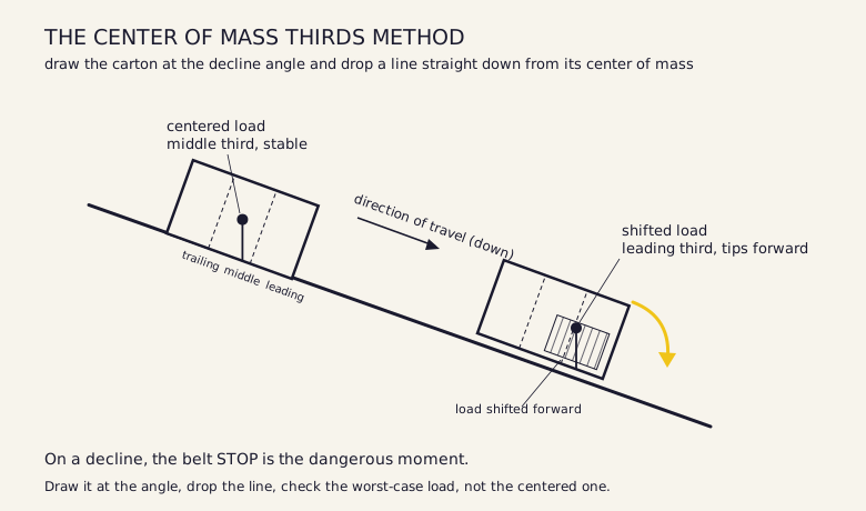
Here's a validation you can run in CAD and in front of a customer. Draw the carton at the incline or decline angle. Divide its length into three equal segments with two lines, a leading third, a middle third, a trailing third. Then drop a line straight down from the center of mass to the incline surface. Land it in the middle third and the package is generally stable; land it in the leading third and it tips forward; land it in the trailing third and it tips backward. For a 12-inch carton the segments are 4 inches each, and the center-of-mass line has to fall inside the middle 4 inches.
The catch is the load. For an evenly loaded carton the center of mass sits at the geometric center. For an unevenly loaded one it shifts toward the heavier end, so you draw the worst case, not the centered case. The thirds method complements the Box Tumbling calculation, it doesn't replace it: when the two agree, confidence is high; when they disagree, the design needs more scrutiny. Its real power is the conversation. A customer who watches the center-of-mass line fall into the leading third understands instantly why the angle has to come down, faster and more convincingly than any tumble-angle number ever gets there.
The same carton, two loads: centered stays in the middle third, shifted forward crosses into the leading third and tips.
PRO TIP | MC
If a Box Tumbling result puts you anywhere close to the limit, then draw the worst-case loaded carton at the angle in CAD and run the thirds method as a second check, using the shifted load, not the centered one. Tradeoff: five more minutes in CAD. Verify: if the center-of-mass line falls anywhere near the boundary between the middle and the leading third, bring the angle down. Close to the limit isn't the same as within it once inertia and load shift are in the picture, and five minutes now beats five days fixing a tumble in the field.
Gravity pitch, spirals, lifts, and mezzanines
Gravity pitch is the slope of a non-powered roller conveyor, the minimum slope that lets product travel under its own weight. It isn't a fixed number. A light empty carton needs more pitch than a heavy full one, because friction weighs more heavily against the little bit of gravity a light box has to work with. Gravity roller conveyors are typically pitched 2 to 8 inches of fall per 10-foot section, depending on the unit load, the roller style and spacing, and the lubrication, with a minimum of three rollers under the product at all times. Confirm the pitch against the actual product mix, not a generic guideline: too little and product stalls partway down, too much and it runs away at the end of the run.
Above that sits the elevation-change toolkit, the vertical transport equipment, and at this stage you meet it as a set of categories with the package question attached to each. Vertical transport is any equipment that carries product between levels. A spiral changes elevation in a small footprint. A vertical lift moves product straight up or down between levels. Mezzanine integration is where a powered decline brings product off an upper deck down to the ground-floor system. Choosing a spiral or a vertical lift against the alternatives is specialty elevation-equipment selection, and that's Lesson 17. The structural design of the mezzanine deck itself sits with the building, not the conveyance, so it's out of scope here. What's in scope is the package: what every one of these transitions asks it to survive.
RIVERSIDE PROJECT
Zone A picks on the second floor, and its cartons have to get down to the ground-floor system. That's a powered decline, and it's the piece Michael flagged on the walk.
"That mezzanine edge is going to be your challenge. Whatever comes down from up here has to land somewhere before it can go south. You have got about 40 feet of horizontal run from the mezzanine edge to where the ground floor zone ends. After that you are in the main aisle. Forklifts run that aisle all shift."
The mezzanine deck is at 16 feet above finished floor with about 40 feet of run. Work out the steepest decline angle that fits in that run, then check every product in the design envelope against its tumble limit. Watch the Tall Case, the 10 x 8 x 14 apparel box, 14 inches tall on an 8-inch base, the tippy one. Draw it at your decline angle and run the thirds method on it with the load shifted forward, name the stop at the bottom as the dangerous moment, and note the pitch for any gravity section at the base of the drop, 2 to 8 inches per 10 feet, three rollers minimum. If the Tall Case can't safely ride the angle your geometry allows, don't assume it works out. Document it and bring Dana the options.
FOREST THROUGH THE TREES
Every transition in this lesson is the same move: run the static number, then ask what the package feels once the belt, the load, and gravity are all acting at once. The curve width lands on the equipment schedule and the drawing. The decline angle sets the elevation profile of the whole system, which touches structure, guard heights, and sight lines downstream. The calculators give you the starting point; the judgment about what they don't model is the part that makes a design work. Carry the curve width, the decline angle, and the ramp you're about to meet into everything that follows. The geometry the package has to survive is the geometry the next lesson inherits.
CHECKPOINT
Your layout has a 90-degree curve at a 32.5-inch inside radius, and the largest carton in the mix is 22 by 15. The mix also includes non-rigid padded mailers. The curve output pushes the system wider than the straight sections need, and the cost target wants a narrower run downstream. Decide whether the guardrail taper is acceptable for this specific mix, and defend the decision.
You've decided a controlled VFD ramp rate is needed on a decline to protect a tippy carton. A coworker says once the ramp is dialed in on the drive, the job is done. Explain what's incomplete about that view: what kind of parameter the ramp rate actually is, and why the conveyors immediately before and after the ramp both have to account for it.
CONTROLS CORNER
The fix for the inertial energy you just met is partly mechanical margin and partly a controls setting: the VFD ramp rate. Ramp rate is how fast the drive brings the belt from stopped to speed and back down. A slower ramp means a gentler start and a gentler stop, which means less peak inertial force on the package at exactly the two moments it wants to tip. Here's the control reality. That ramp time isn't a knob someone turns in the field once and forgets. It's a PLC parameter that has to be specified in the controls design, and it has to be compatible with the conveyors on either side, because during the ramp the belt isn't at operating speed and product is still moving across the boundary. The ramp time that protects your carton on the decline becomes a number on the installation drawing. How it's set and tuned is Part V, in Lesson 20. For now, know that the angle you designed and the ramp you need are two halves of the same decision.