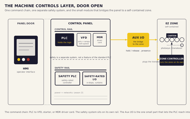
Upstream, the system already knows what the carton is and where it sits, and a layer above already decided where it goes. None of that moves a single roller. Between the decision and the motion sits the machine controls layer: the PLC, the drives, the driver cards, and a safety system that can override all of them faster than a person can pull a hand back.
This is the layer that turns a number into a moving belt, a firing divert, a held zone. It's also the layer that has to do it the same way ten thousand times a shift without hurting anyone standing near it. Earlier in Part V you built the control philosophy and the sensing. This lesson is the implementation, the part where those concepts become the panel.
By the end of this lesson you should be able to trace how a routing decision becomes physical motion through the PLC, the drives, and the driver cards, map every Aux I/O point in a system before the panel is built, explain a safety PLC's zoning, reset, and safe-state behavior, and name the tagging, alarm, and state-machine discipline that keeps a controls package maintainable.
The PLC holds the logic and issues the commands. On its own it doesn't turn anything; it decides. Motor controls are what turn a command into rotation, and there's more than one kind. A VFD sets and ramps a belt's speed, and that ramp rate is itself a setpoint, the same VFD parameter the Part IV controls corners kept pointing at this lesson. A motor starter switches a fixed-speed AC motor on and off, full voltage, no speed control. An MDR driver card drives and stops an electric motor-driven-roller zone on a low-voltage signal. And the HMI is the screen on the panel door. It's where an operator sees what the system's doing, starts and stops zones, reads a fault, and acknowledges an alarm. You care about it because it's where a person actually meets the controls, so its screens have to match how the operation really runs, not how the drawing looks.
The PLC orchestrates all of them. It reads the sensing layer, applies its logic, and commands the drives, while the self-contained EZLogic zones handle their own accumulation without the PLC touching every zone. That's the division of labor worth carrying out of this section. The PLC owns the decisions that cross zones and equipment. The zone controllers own the decisions that happen inside a single zone. Keep that boundary clean and the program stays small. Blur it and the PLC ends up micromanaging every roller, which is exactly what the EZ zones were built to spare it.
You selected the decline's ramp rate back in Part IV as a package-handling decision. Here it isn't a decision anymore; it's a documented setpoint, a number that rides into the design package. The final belt-speed arithmetic is Lesson 25.
Lesson 13 told you the Aux I/O module exists. This is where it gets wired. The module plugs into a zone's transducer port on one end, which connects it to the zone controller and the photoeye, and into the PLC control panel on the other. That gives the PLC two capabilities it wouldn't otherwise have on a self-contained EZ conveyor: it can command that specific zone to hold or release, and it can read whether a package is present in that zone.
You need one at every point where the PLC has to talk to a zone or listen to one. That's every end-of-conveyor zone feeding a non-EZ device, a sorter induction, a transfer, a scanner; every PLC-commanded hold pending a scan result or a downstream-ready signal; every zone whose presence the PLC needs for a routing or timing decision; and every merge-entry zone the PLC sequences. The rule is short: if the PLC needs to talk to the zone or listen to the zone, it needs an Aux I/O.
It doesn't always need a PLC at all. A pack-station zone can wire a footswitch straight into the Aux I/O to pause the zone while an operator loads product, configured locally in the zone controller, no PLC in the loop. Either way the discipline is the same: map every Aux I/O point on paper during design, before the panel is built. Found during commissioning, a missing Aux I/O is a panel modification at the worst possible time.
The zone sizing, count and length, was Lesson 13, and so was the release-mode selection, singulate, slug, or cascade. Here those zones already exist. You're placing the Aux I/O on them and carrying the release mode forward as a documented setpoint.
Missing an Aux I/O point during design and discovering it at commissioning. Every EZ zone that needs to talk to or listen to the PLC needs one, and the ones people miss are the quiet ones: the end-of-conveyor zone feeding a transfer, the merge-entry zone nobody flagged. Find it during commissioning and you're cutting into a finished panel on a live schedule. Map every point on paper before the panel is built.
If you're designing any system with EZ accumulation, then do a zone-by-zone walk of the whole layout and write down every zone that has to talk to the PLC or listen to it, before the panel design is released. Tradeoff: it's a tedious pass and it feels like something you could catch later. Verify: count your Aux I/O points against your end-of-conveyor zones, your PLC-commanded holds, your presence reports, and your merge entries. If those four lists don't reconcile with your Aux I/O count, you've missed one, and later is a panel mod, not a line item.
When you get to the end of an EZ conveyor and it is feeding something that is not an EZ conveyor, you need an Aux I/O module on that last zone. The PLC needs to be able to tell that zone to hold product and to know when a package is sitting there waiting. Without the Aux I/O, the zone does not know to wait and the PLC does not know what is happening in that zone. Map your Aux I/O points during the design phase, not during commissioning. Every end-of-conveyor zone, every zone that needs a PLC-commanded hold, every zone that feeds a non-EZ piece of equipment needs to be identified before the panel is built. Finding a missing Aux I/O during commissioning costs time and sometimes requires a panel modification. The Aux I/O module is a small component with a large impact. It is easy to overlook in the design. Make it part of your zone-by-zone review on every EZ system you design.

Safety doesn't run on the standard PLC. E-stops, light curtains, and interlocks run on a separate safety-rated controller and safety-rated I/O, wired with safety-rated interlock devices rather than standard switches. A standard limit switch on a safety gate isn't a safety device, and treating it like one is the kind of shortcut that turns up in an incident investigation. Which regulation governs the guarding, and the guarding standard itself, is Lesson 27; here it's the controls architecture.
Three ideas carry this layer. Zoning: the system is divided into safety zones, so an e-stop or a trip in one zone stops that zone and its hazard, not necessarily the whole plant. A jam in one aisle shouldn't dark the building. Reset logic: a zone that has tripped doesn't restart on its own when the condition clears. It needs a deliberate, located reset by a person, so nothing surges back to life while someone's hands are in it. Safe-state: the designed behavior on a trip, spelled out ahead of time, what stops, what holds, and what's allowed to coast, so a stop is predictable instead of a scramble.
This is where Lesson 13's fail-safe zone mode lands. The factory default is signal-to-stop: the signal is what commands the hold, so a lost signal, a pulled connector, turns loose whatever the zone was holding, uncontrolled. The configuration to specify is zone-stop, signal-to-release: the zone holds unless the signal commands release, so a lost signal leaves product sitting in place. On a live system connectors get pulled, so the configuration you specify matters more than the default you inherited.
The guarding compliance, the pull-cord engineering, the reach-and-height questions, robot and cobot guarding, and the map of which safety regulation applies where are all Lesson 27. How the safety messages ride the network is Lesson 21. This section is the safety controls architecture: how the safety system is wired and how it behaves.
A maintenance tech unplugs one Aux I/O to trace a fault, on a zone that's holding four cartons. Walk what happens if that zone is set signal-to-stop, and what happens if it's set signal-to-release. Then decide which one you'd want to be the default on every job you ever design, and why the default matters more than the exception.
A controls package that works and a controls package a maintenance tech can keep working are two different things, and the gap between them is discipline. This is the clearest place in the program that controls isn't a slogan; it's a set of habits that decide whether the next person can read what you built.
Tagging conventions. Every device and signal carries a consistent, structured name, so the PLC program, the electrical drawing, and the HMI all call the same thing the same thing. A tech reading an alarm at two in the morning should be able to find that device on the drawing without a decoder ring.
Alarm philosophy. Alarms are designed, not accumulated. Each one is prioritized and actionable, it tells the operator what happened and what to do, and the system is built so a single fault doesn't bury the screen under fifty alarms that hide the one that matters. That discipline is what the alarm rationalization in Lesson 23 builds on.
State-machine design. Equipment lives in defined states, stopped, running, faulted, e-stopped, with defined transitions between them. Behavior stays predictable, and a fault has a known path back to running instead of an improvised one.
The operator-facing alarm rationalization and the runtime root-cause diagnostics are Lesson 23. Here you set the discipline; Lesson 23 puts it to work when the system faults.
Back to Riverside. The sort decision belongs to the WCS, but the PLC executes the divert. The mezzanine decline runs on a VFD, and its ramp rate, carried from your Part IV decline design, is a documented setpoint now, not a knob someone turns at startup. The E24 zones run on MDR driver cards. The safety PLC zones the system so the forklift-crossing hazard and the pull-cord e-stops each stop the right zone, each with a located, deliberate reset.
Walk the Riverside layout and write down every zone that needs an Aux I/O: the end-of-conveyor zones feeding the sorter induction, the merge-entry zones, any zone the PLC has to hold. Confirm every accumulation zone is configured zone-stop, signal-to-release, not left at the factory default. Then start the setpoints list: belt speeds by section, the VFD ramp rate at the decline, the PLC delays at the transfers, the release mode on each zone, and the fail-safe configuration, stated. Date it and keep it with your Riverside notes.
This is the layer where a decision finally becomes motion. Everything above it, the philosophy, the sensing, the routing, produces instructions; none of it moves a roller. The machine controls layer is where those instructions become a turning belt, a firing divert, a held zone, and a stop you can trust. You carried in the system's eyes from Lesson 19. You carry out the PLCs, the drives, and the safety architecture, and next you power them and wire them together in Lesson 21. Every setpoint you specified here, every ramp rate and release mode, is a number that gets written down now or gets defaulted at startup, where the system quietly underperforms and nobody can say why.