Part V. Lesson 23. Recovery, Diagnostics, and the Operator.
Everything across this part designed the system for the day it works: the scanner reads, the WMS answers in time, the divert fires, the carton lands at the right door. This lesson designs it for the day it doesn't, and that day always comes. A photoeye stays blocked and a zone jams. A lane fills during a wave. A barcode won't read. The WMS drops for ninety seconds at the worst moment. None of those are exotic. They're Tuesday.
What separates a system an operator trusts from one they fight is whether every failure has a designed destination and a designed recovery, or whether it stops the whole line and waits for someone to figure out what happened. Recovery is engineering, not improvisation.
A jam is detected when a photoeye that should clear inside a defined time window stays blocked past it; the PLC stops that zone and alerts the operator. That response is deliberately blunt, because a jam that keeps feeding is a jam that grows.
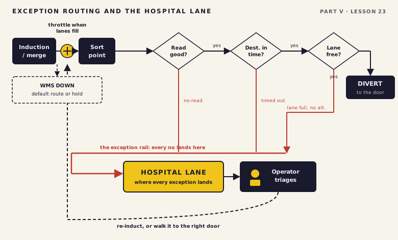
A lane-full condition is detected when the photoeye at a sort lane's entry stays blocked, so the lane can't take more product. The carton headed there has nowhere to divert, so the system sends it elsewhere: a backup lane, recirculation on a loop, or the destination of last resort, the hospital lane.
Designing the hospital lane as a placeholder rather than a throughput element. It's easy to draw the exception box at the end of the sorter and move on, because during initial sizing it never seems to matter. Then the no-reads and rejects show up at the rate they always do, the placeholder can't clear them, and it backs up into the sorter and creates a secondary jam that stops everything.
Anti-gridlock control prevents it by correlating induction rate to clearance rate. If the lanes are filling and the loop is loading up, the system throttles or stops new induction before it runs out of path. The PLC watches lane status and loop load continuously. That's the controls half, and it's where most engineers stop.
Here's the half they miss. The PLC can only throttle if the layout gave it enough physical buffer to absorb product while the throttle takes effect. Leave no runway between the induction gate and the loop, and no PLC logic prevents gridlock under heavy load. That buffer is floor space, not code.
The way the controls interact with incoming product on a sorter has to be directly correlated to the rate at which the sorter can get rid of product or divert product. If you are inducting faster than the sorter can clear, you will fill the loop, fill the lanes, and have nowhere for the product to go. That is gridlock. The controls must throttle induction based on what is happening downstream, not just run at maximum speed because product is available upstream.

Example only. The percentages below are placeholders to show the method, not measured rates for any real system.
It's 2 AM. A zone's stopped and the HMI is stacked with alarms. You don't want a wall of red; you want one line naming which photoeye stayed blocked and where, so you walk to it, clear it, hit a reset you can find, and watch the zone come back without anything lurching. Design for that person on that shift, not for the demo where nothing goes wrong.
Next: Where does the calculated answer stop being true, and how much margin does it need?